
Introduction:
In the realm of electronic instrumentation, the oscilloscope stands as a pivotal tool, revolutionizing the way engineers and technicians analyse and troubleshoot electronic signals. This article aims to delve deep into the intricacies of oscilloscopes, covering everything from their definition to various types, applications, and essential tips for optimal usage.
What is an Oscilloscope?
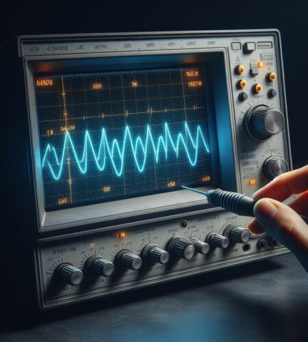
An oscilloscope is a sophisticated measuring tool that graphically represents electrical signals over time. It provides a visual representation of voltage changes in a waveform, enabling users to comprehend intricate details of electronic signals that might be otherwise elusive.
History of Oscilloscope:
The true birth of the oscilloscope can be attributed to the work of Karl Ferdinand Braun and C. Francis Jenkins in the early 20th century. By the 1930s, the Cathode Ray Oscilloscope (CRO) emerged, enabling scientists and engineers to visualize electrical signals in real-time. This revolutionary device provided a graphical representation of waveforms, marking a significant leap forward in electronics. The mid-20th century witnessed the widespread adoption of analog oscilloscopes. These instruments, employing CRT technology, became essential tools in laboratories and engineering fields. Engineers could now observe and analyze electronic waveforms with improved accuracy and precision. The 1980s ushered in the era of digital oscilloscopes, leveraging advancements in digital signal processing (DSP). This transition marked a paradigm shift, offering users enhanced features such as waveform storage, mathematical functions, and improved measurement accuracy. Digital oscilloscopes became synonymous with versatility and efficiency.
Types of Oscilloscopes:
- Analog Oscilloscope (AO): Analog oscilloscopes are electronic test instruments that employs analog components, typically cathode-ray tubes (CRTs), to visually display electrical waveforms in real-time. It is known for its simplicity and ease of use, making it suitable for basic waveform observation. It lack the advanced features and digital processing capabilities found in their digital counterparts but remain cost-effective for simple signal analysis.
- Digital Oscilloscope (DO): A digital oscilloscope is an advanced electronic test instrument that utilizes digital signal processing (DSP) to capture, analyze, and display electrical waveforms. Unlike AO, it offers a wide range of features, including precise measurements, advanced triggering, and the ability to store and recall waveforms for in-depth analysis. These are versatile tools suitable for complex applications in electronics and provide a detailed representation of signals in both time and amplitude domains.
- Cathode Ray Oscilloscope (CRO): Cathode ray oscilloscopes (CRO) are electronic instrument that employs a cathode-ray tube (CRT) to display and analyze electrical waveforms in real-time. It works by deflecting an electron beam onto a phosphor-coated screen, producing a visual representation of the input signal. CROs are widely used for observing and measuring voltage variations in electronic circuits, providing a valuable tool for engineers and technicians in various applications.
- Mixed-Signal Oscilloscope (MSO): A MSO is an advanced test instrument that combines the capabilities of a DO with those of a logic analyzer. It allows simultaneous visualization and analysis of both analog and digital signals in electronic systems. MSOs are particularly useful for debugging complex circuits, providing engineers with a comprehensive tool for troubleshooting and waveform analysis in mixed-signal environments.
- Storage Oscilloscope: A storage oscilloscope is an electronic test instrument that captures and stores waveform data for subsequent analysis. it allows users to review and analyze previously captured signals, making it ideal for identifying intermittent or rare events in electrical systems. Storage oscilloscopes are valuable tools in troubleshooting and diagnosing complex electronic circuits where capturing transient signals is crucial for in-depth analysis.
- PC-Based Oscilloscope: A PC-based oscilloscope is an oscilloscope that relies on a computer for its display and processing capabilities. Connected through interfaces like USB or Ethernet, it leverages software applications to capture, analyze, and visualize electrical waveforms. it offer flexibility, portability, and the ability to take advantage of the computer’s processing power for advanced features and updates.
- Digital Phosphor Oscilloscope (DPO): A Digital Phosphor Oscilloscope (DPO) is an advanced test instrument that utilizes digital signal processing and a special phosphor display to provide enhanced visualization of fast-changing waveforms. It offers a more detailed and colorful representation of signals, making it easier to identify and analyze complex signal behaviors. DPOs are particularly valuable in applications where capturing and understanding transient events is crucial, such as in high-speed digital design and communication systems.
- Handheld Oscilloscope: A handheld oscilloscope is a compact and portable electronic test instrument designed for on-the-go use. These devices provide engineers and technicians with the convenience of analyzing waveforms in the field or in tight spaces. While typically offering less performance than benchtop models, These are valuable tools for quick measurements and troubleshooting in various applications.
- Sampling Oscilloscope: A sampling oscilloscope is a specialized instrument designed for the analysis of high-frequency signals. It utilizes a sampling technique to capture and reconstruct waveforms from multiple data points. These are particularly useful in applications involving very fast signals, such as telecommunications and high-speed digital design, providing accurate insights into high-frequency waveform behavior.
- FFT Oscilloscope: An FFT (Fast Fourier Transform) oscilloscope is an instrument equipped with a built-in FFT function for frequency domain analysis. It allows users to transform time-domain waveforms into their frequency components, providing insights into the spectral characteristics of signals. FFT oscilloscopes are valuable for analyzing the frequency distribution of complex waveforms in applications such as audio processing, communications, and vibration analysis.
- High-Performance Oscilloscope: A high-performance oscilloscope is an advanced electronic test instrument tailored for demanding applications and research. It typically offers a combination of high bandwidth, fast sampling rates, and advanced features, providing precise measurements and detailed analysis of complex waveforms. Widely used in research and cutting-edge technologies, high-performance oscilloscopes are crucial tools for engineers and scientists working on projects requiring superior measurement accuracy and capabilities.
How to Use an Oscilloscope:
Using an oscilloscope may seem daunting at first, but with a step-by-step approach, it becomes a powerful tool for visualizing and analyzing electronic signals. Here’s a beginner’s guide on how to use an oscilloscope:
- Power Up: Turn on the oscilloscope and let it warm up for a few minutes to ensure stable operation.
- Connect the Probe: Attach the oscilloscope probe to one of the channels on the front panel. Connect the probe’s ground clip to the ground reference point of the circuit.
- Adjust Voltage Scale: Set the voltage scale on the vertical axis to an appropriate level for the signal you’re analyzing. This is usually adjusted using the VOLTS/DIV knob.
- Adjust Timebase: Set the timebase on the horizontal axis to an appropriate time scale. Use the TIME/DIV knob to control the speed of the waveform display.
- Adjust Trigger Settings: Set the trigger level and trigger source. The trigger stabilizes the waveform display. Adjust the trigger level until the waveform stabilizes on the screen.
- Probe Compensation: Many oscilloscope probes come with a compensation adjustment. Use the probe’s compensation tool to ensure accurate signal representation.
- Acquire and Display: Connect the probe tip to the point in the circuit where you want to measure the signal. The oscilloscope will display the waveform in real-time.
- interpret the Waveform: Understand the characteristics of the waveform, such as amplitude, frequency, and shape. This helps in diagnosing and troubleshooting electronic circuits.
- Measure Parameters: Most oscilloscopes have built-in measurement functions. Use these features to measure peak-to-peak voltage, frequency, and other parameters.
- Use Cursors: Cursors help measure specific points on the waveform. Use them to accurately measure time intervals, voltages, and other parameters.
- Explore Additional Features: Familiarize yourself with additional features like FFT (Fast Fourier Transform) for frequency domain analysis, and other advanced functions specific to your oscilloscope model.
- Save and Document: If needed, capture screenshots or save waveforms for documentation. Some oscilloscopes allow you to save data to external devices.
- Power Down: When finished, power down the oscilloscope. If you’ve adjusted any settings, return them to default for the next user.
How An Oscilloscope works?
It works by visualizing and measuring electrical signals over time. Here’s a simplified explanation of how it operates:
- Input Signal: It receives an electrical signal through its input channels. This signal can be from various sources, such as electronic circuits, sensors, or devices under test.
- Vertical Amplification: The input signal is first passed through a vertical amplifier. This amplifier adjusts the amplitude (voltage) of the signal, allowing the user to control the vertical scale on the display.
- Timebase Control: The timebase control determines the horizontal scale, representing time. It controls the rate at which the oscilloscope sweeps the display horizontally. This setting allows users to observe different time intervals of the signal.
- Cathode-Ray Tube (CRT) or Display Panel: In analog oscilloscopes, a CRT is commonly used. In digital oscilloscopes, a digital display panel is employed. For CRT-based oscilloscopes, an electron beam is generated and deflected vertically and horizontally to create a visible trace on a phosphor-coated screen.
- Deflection Plates: The vertical and horizontal deflection plates control the movement of the electron beam on the CRT screen. The vertical plates handle the amplitude (voltage) of the signal, while the horizontal plates control the timebase.
- Timebase Triggering: To provide stable and synchronized waveforms, it employs a trigger system. The trigger detects a specific point on the input waveform and initiates the horizontal sweep of the display.
- Displaying the Waveform: As the electron beam moves across the CRT screen or digital display, it draws the waveform of the input signal. The vertical position represents voltage, and the horizontal position represents time.
- Measurement and Analysis: This tool often include measurement features such as voltage measurements, frequency analysis, and other parameters. Digital oscilloscopes can perform additional processing and analysis using their digital signal processing capabilities.
By observing the displayed waveform on the screen, users can gain insights into the behavior of the electrical signal, identify anomalies, and perform various measurements for analysis and troubleshooting.
Symbols for an Oscilloscope:
Oscilloscopes use various symbols on their control panels to represent different functions and settings. Here are some common symbols associated with oscilloscopes:
| Symbol | Representation | Function |
|---|---|---|
| Square Wave Symbol | A square wave symbol | Indicates the type of waveform being displayed, often for input signal selection. |
| Sine Wave Symbol | A sine wave symbol | Represents the type of waveform being displayed, commonly used in input signal selection. |
| Triangle Wave Symbol | A triangle wave symbol | Indicates the type of waveform being displayed, typically for input signal selection. |
| DC Offset Symbol | “DC” with an arrow | Used to set the direct current (DC) offset on the waveform. |
| Ground Symbol | A horizontal line with a downward-pointing arrow | Identifies the ground reference point. Connect the probe’s ground clip to this point in the circuit. |
| Trigger Level Symbol | “T” with an arrow | Adjusts the trigger level, helping to stabilize the waveform display. |
| Timebase Control Symbol | “TIME/DIV” with arrows pointing left and right | Adjusts the timebase, controlling the speed of the waveform display along the horizontal axis. |
| Voltage Control Symbol | “VOLTS/DIV” with arrows pointing up and down | Adjusts the voltage scale, controlling the amplitude of the waveform along the vertical axis. |
| Probe Compensation Symbol | “COMP” or a similar label | Indicates the control for compensating the oscilloscope probe to ensure accurate signal representation. |
| Auto/Set Function Symbol | “AUTO” or “SET” button | Initiates automatic or preset adjustments for various settings, such as voltage, timebase, and trigger level. |
| Channel Select Symbols | “CH1” and “CH2” | Selects the active channel for waveform display and analysis. |
Note: The actual symbols on an oscilloscope may vary depending on the model and brand. Refer to the oscilloscope’s user manual for specific details on the symbols used.
Applications of Oscilloscopes:
This tool find extensive applications in various industries, with particular relevance in:
1.Electronics and Electrical Engineering:
- Essential for debugging and troubleshooting electronic circuits.
- Facilitates the observation of signal distortions, frequency, and voltage levels.
2.Automotive Industry:
- Automotive Oscilloscopes are specialised tools for diagnosing and analysing electrical systems in vehicles.
- Helps identify issues in sensors, ignition systems, and communication networks.
3.Research and Development:
- Crucial for designing and testing electronic circuits in laboratories.
- Enables researchers to validate theoretical models and ensure proper functionality.
Key Features of Notable Oscilloscopes Brands:
1.Tektronix Oscilloscope:
- Renowned for its innovation and reliability.
- Offers a wide range of oscilloscopes catering to diverse user requirements.
2.Hantek Oscilloscope:
- Known for providing cost-effective solutions without compromising on performance.
- Gaining popularity for their user-friendly interfaces.
Tips for Optimizing Oscilloscopes Usage:
- Understanding Waveform Basics: Familiarize yourself with waveform characteristics such as amplitude, frequency, and phase.
- Proper Grounding: Ensure proper grounding to prevent noise and improve measurement accuracy.
- Adjusting Timebase and Voltage Scale: Set the timebase and voltage scale appropriately for accurate signal analysis.
- Utilizing Trigger Functions: Use trigger functions to stabilize and capture specific events in the waveform.
Conclusion:
In conclusion, oscilloscopes play an indispensable role in the field of electronics, providing engineers and technicians with valuable insights into the behaviour of electronic signals. From understanding the basics to exploring various types and applications, this comprehensive guide aims to empower users with the knowledge required for efficient oscilloscopes usage. Whether you are working in electronics, automotive diagnostics, or research, a thorough grasp of oscilloscopes functionalities is crucial for mastering the art of signal analysis.
Learn more about various instruments or tools to enhance your expertise.
Measure Things using a Oscilloscope:
How to Measure Frequency and its related aspects
Frequently Asked Questions (FAQs)
What is an oscilloscope, and how does it work?
It is a measuring tool that visually represents electrical signals over time, providing a graphical display of voltage changes in a waveform. It works by capturing and displaying electrical signals on a screen, allowing users to analyze the behavior and characteristics of the signal.
What are the different types of oscilloscopes available?
There are three main types:
- Analog Oscilloscope: Utilizes a cathode-ray tube (CRT) to display continuous waveforms.
- Digital Oscilloscope: Uses digital signal processing for precise waveform analysis, offering advanced features.
- Cathode Ray Oscilloscope (CRO): The traditional type, featuring a CRT for waveform display, commonly used for educational purposes.
Can you explain the significance of automotive oscilloscopes?
These are tailored for diagnosing electrical issues in vehicles. They help identify problems in sensors, ignition systems, and communication networks, playing a crucial role in maintaining and repairing automotive electronics.
Are oscilloscopes suitable for educational purposes?
Yes, CROs are commonly used for educational purposes. They provide a visual representation of electronic signals, aiding students in understanding waveform characteristics and electrical principles.
Can oscilloscopes be used for research and development?
Absolutely, This tool is one of an invaluable tools in research and development laboratories, allowing researchers to design, test, and validate electronic circuits, ensuring their proper functionality and performance. You can purchase it in reasonable price from Amazon.
Categorized in: